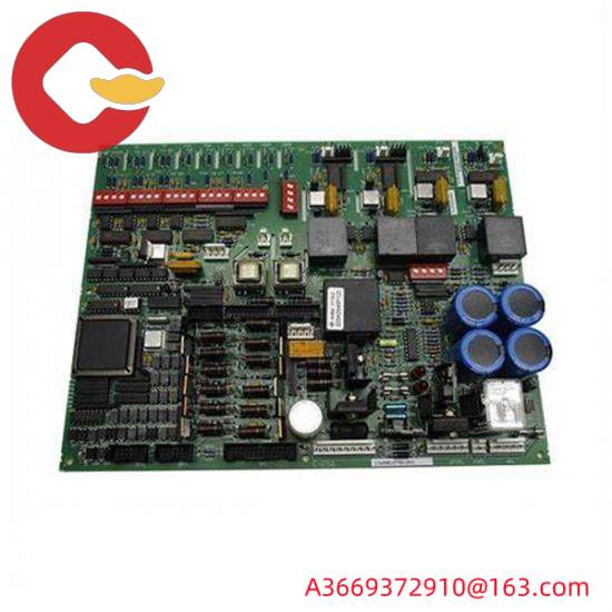
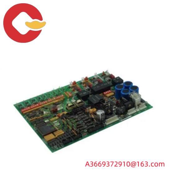
The GE DS200DCFBG1BKC is a Mark V series power supply board. When mounted in a drive, the board provides power to the case fans as well as the system’s control-level power supply. In GE’s drive system, the board is compatible with DC2000, AC2000, FC2000, CB2000 and ME2000 series drives. The Mark V turbine control system family to which the DS200DCFBG1BKC power board belongs has specific applications in control and management systems for compatible steam, gas and wind turbine automatic drive components, and is considered a legacy family from General Electric, as its manufacturing has been discontinued for many years after its first release. His Mark V series of DS200DCFBG1BKC printed circuit boards, or PCBS for short, is also considered one of the last lines of GE products to feature the company’s patented Speedtronic style control system technology. Although the DS200DCFBG1BKC PCB itself can be defined as a power board, it is not the original development product of this function in Mark V; This will be the DS200DCFBG1 parent power board missing all three important product revisions of this DS200DCFBG1BKC product.
Hardware tips and specifications
As with any product in the Mark V series, this DS200DCFBG1BKC printed circuit board introduces hardware components and component specifications by inserting various functions into its normal Mark V Series components, thus distinguishing it from different Mark V Series PCBS. The nominal rated source input of the DS200DCFBG1BKC board can safely measure voltages between 38 and 115VAC. The output frequency produced by the card can measure any frequency between 0 and 500 kHz, depending on the input voltage. Find five individual circuits on DS200DCFBG1BKC. These circuits include control level power supply circuits, drive circuits, motor excitation power supply circuits, and AC and DC monitoring circuits. The diagnostic information of the fuse on the drive is presented to the user via two LED indicators and one neon indicator. Three protective fuses are integrated into the circuit board to protect the current from interruption. Checking voltage levels in the board is simple using one of the five test points on the card. Users are provided with a number of configurable Settings to suit the specific needs of the job. The 12 jumpers and 7 DIP switches on the board can be configured according to user requirements.

Circuit boards and drivers contain installation parameters outlined by General Electric, which should be followed. These guidelines will protect the entire device from any accidental damage. Please refer to the device’s data sheet and manual for a complete guide to wiring and mounting boards. In general, it is critical to disconnect all power to the DS200DCFBG1BKC printed circuit board and its larger Mark V turbine control System family of automatic drive components before attempting to install or replace the DS200DCFBG1BKC board. Given the potentially lethal surface voltage that can be present on the substrate of this DS200DCFBG1BKC product, it is critical to identify this specific installation parameter even minutes after its larger Mark V-Series drives lose power. Before making any final purchase decision, it is absolutely important to consider the complete revision history of this DS200DCFBG1BKC power supply board, which includes the Class B Functional Product revision, the Class K Secondary Functional Product Revision, and the Class C Graphic Configuration Product revision. All of these revisions could significantly change the performance specifications and base dimensions originally introduced for this DS200DCFBG1BKC product. The members of the Mark V Series are technically supported by their original manufacturer, General Electric. AX Control’s experienced and knowledgeable sales team is happy to help you with all your automation needs. For pricing and availability of DS200DCFBG1BKC and other parts, as well as repairs, please contact our staff by email or phone.
FAQ about DS200DCFBG1BKC
Where can I find information about the DS200DCFBG1BKC application data?
The DS200DCFBG1BKC manual has a chapter, the GEI-100028 Manual, on application data. This chapter in the DS200DCFBG1BKC manual includes the following information: DS200DCFBG1BKC hardware, configurable jumper and DIP switch, LED on DS200DCFBG1BKC And neon light, DS200DCFBG1BKC connector, DS200DCFBG1BKC logo, DS200DCFBG1BKC warranty, procedures for replacing DS200DCFBG1BKC board, and DS200DCFBG1BKC EE parameter adjustment. For a copy of this manual, the GE Industrial Control System Power Board Manual, please request Manual GEI-100028.
What is the voltage of the control level power supply on DS200DCFBG1BKC?
The voltage of the control-level power supply circuit on the DS200DCFBG1BKC is +5, +/-15, and +/-24 VDC.
What does the power output DS200DCFBG1BKC protect?
The power outlet on the DS200DCFBG1BKC has anti-short circuit fuses F2 and FU3 protection.